Daniel Tkachov
Published June 22, 2023
This blogpost was made for three reasons: to show how I created my
chaotic attractor simulator, the thought process behind it, and to
refine my code. I wrote is as a pseudo-guide, so that in the future when
I revisit this project I’ll be able to get up to speed on new additions
very quickly. The simulation started simply by rendering a point inside
a scene before complexity was gradually added to turn it into the final
simulation, so lots of code was rewritten and deleted as according to
what was needed.
Starting at the very beginning, after creating a folder to store the
work in, I have to install three.js, which is the graphics rendering
library that I’ll be using for this project. this is done by navigating
to the filepath in the command line and typing in
npm install three. After this, I create 3 files:
index.html, index.scss, and attractor.js.
Finally, the code writing can begin. I began this project by breaking
it down into many smaller steps. Before I can have many lines whizzing
around, I have to be able to make a few points go around first. Before
that, I have to be able to render a single point.
I begin by importing three.js and following the documention. “To
actually be able to display anything with three.js, we need three
things: scene, camera and renderer, so that we can render the scene with
camera.” I started off with creating these elements:
import * as THREE from 'three'

let scene, camera, renderer;
scene = new THREE.Scene();
camera = new THREE.OrthographicCamera(-20, 20, 15, -15, 0, 1000);
renderer = new THREE.WebGLRenderer();
renderer.setSize( window.innerWidth, window.innerHeight);
document.body.appendChild( renderer.domElement );
The parameters for the OrthographicCamera dictate the frustum. The
orthographic/isometic camera shows the world from a different
perspective relative to how we as people perceive the world. In our
vision, when an object is further away, it becomes smaller. With an
isometric view, it doesn’t matter how far or near an object is; it will
always occupy the exact same amount of space on the screen. This is
perfect for my simulation as I want to see all the dots whizzing around,
not just a few of them.
Perfect! I have the scene, camera and renderer. Now would be as good
a time to compile the file and see if we can open it without errors in
the browser. In order to use local imports, I have to use a JS bundler
as the local files cannot be accessed from the browser. I decided to use
webpack due to its popularity and ease of use. I installed webpack and
webpack-cli using npm install webpack webpack-cli. This is
to make a quick script that will collect all the dependencies needed for
the code and put it all into a single file that can then be deployed to
our web server. In our package.json file, I made this script:
"scripts": {
    "build": "webpack",
    "test": "echo \"Error: no test specified\" && exit 1"},
And webpack neds to know what files need to be compiled and where to
export it, so I created a webpack.config.js file:
module.exports = {
    entry: './attractor.js',
    output: {
        filename: 'attractorDist.js',
    },
};
This file will be exported to a new folder titled “dist”, where I’ll
be able to access it. Running npm run build will create the
attractorDist.js file:
webpack 5.86.0 compiled with 4 warnings in 6826 ms
It compiled, now the script has to be called inside the html file to
actually display in the browser:
<script type="module" src="./dist/attractorDist.js"></script>
The setup is now complete, at this point I was able to begin
programming the actual logic that would create the simulation.
Creating the simulation
When originally creating this project, I started off by just trying
to render 1 point. If I could render 1, I could render many many more.
To create the point, I had to give it geometry (the polygons that make
it up) and material (the texture to put on those polygons). I also added
in the wireframe property that will allow me to see a sphere instead of
a blob:
const light_mat = new THREE.MeshBasicMaterial({wireframe: true});
const sphereGeometry = new THREE.SphereGeometry();
The two then had to be made into a point using the THREE.Mesh method,
and added to the scene to be rendered:
const point = new THREE.Mesh(circleGeo, light_mat)
scene.add(point)
The camera also needed to be set in order
camera.position.set( -23, -16, -20 ); // these values were found through trial and error when originally creating the project
Finally, all the building blocks are in place to render a single
point/circle. All that’s left is to actually render it. Taken from the
docs, I used the animate function to render it:
function animate() {
    requestAnimationFrame( animate );
    renderer.render( scene, camera );
}
animate();
And voila! running npm run build and opening the html
page in the browser gave something like this: Note: in this image, the
camera is located at (0,0,-5) and not the values above. 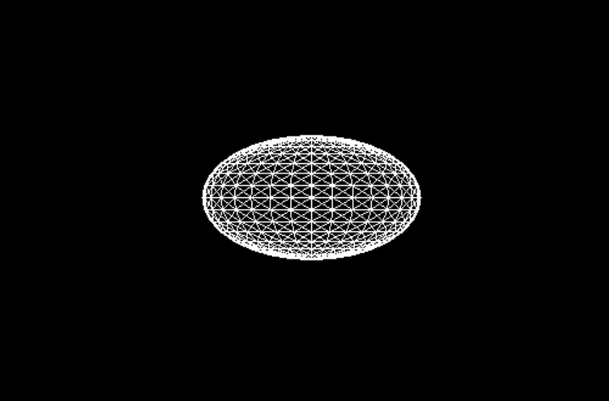 Now that the sphere is rendered, I was able to move
onto the next phase: moving the sphere around. Inside the animate()
function, before the frame is rendered, I added the equations that’ll
change the position of the sphere:
Now that the sphere is rendered, I was able to move
onto the next phase: moving the sphere around. Inside the animate()
function, before the frame is rendered, I added the equations that’ll
change the position of the sphere:
// We'll need to add these variables as well, as they are required for the equations
let alpha = 1.4;
let speed = 0.01;
point.position.x += speed * (-alpha * point.position.x - 4 * point.position.y - 4 * point.position.z - (point.position.y * point.position.y));
point.position.y += speed * (-alpha * point.position.y - 4 * point.position.z - 4 * point.position.x - (point.position.z * point.position.z));
point.position.z += speed * (-alpha * point.position.z - 4 * point.position.x - 4 * point.position.y - (point.position.x * point.position.x));
Since the sphere is automatically placed at 0,0,0 in 3D space, I
randomized its starting location so that it wouldn’t be stuck at 0,0,0
for eternity:
// I added this after making the point
point.position.set(.1,.1,.1)
Now when the project is built, the lone sphere will start flying
around according to the equations. Phenomenal! This is the attractor.js
file so far:
import * as THREE from 'three'

let scene, camera, renderer;
scene = new THREE.Scene();
camera = new THREE.OrthographicCamera(-25, 25, -25, 25, 0, 100);
renderer = new THREE.WebGLRenderer();
renderer.setSize( window.innerWidth, window.innerHeight);
document.body.appendChild( renderer.domElement );

const light_mat = new THREE.MeshBasicMaterial({wireframe: true});
const sphereGeometry = new THREE.SphereGeometry();
let point = new THREE.Mesh(sphereGeometry, light_mat)
point.position.set(.1,.1,.1)
scene.add(point)

camera.position.set( -23, -16, -20 );

let alpha = 1.4;
let speed = 0.01;
function animate() {
    requestAnimationFrame( animate );
    point.position.x += speed * (-alpha * point.position.x - 4 * point.position.y - 4 * point.position.z - (point.position.y * point.position.y));
    point.position.y += speed * (-alpha * point.position.y - 4 * point.position.z - 4 * point.position.x - (point.position.z * point.position.z));
    point.position.z += speed * (-alpha * point.position.z - 4 * point.position.x - 4 * point.position.y - (point.position.x * point.position.x));

    renderer.render( scene, camera );
}
animate();
At this stage, I moved to increasing the number of points that would
be on screen:
let NUM_POINTS = 200
let points = []
for(let i = 0; i < NUM_POINTS; i++){
    let point = new THREE.Mesh(sphereGeometry, light_mat) // this line was moved inside the loops
    point.position.set(Math.random(), Math.random(), Math.random())  // this line has been changed to randomize the positions
    scene.add(point)
    points.push(point)
}
I stored all these points in an array so that it would be easy to
loop over them inside the animate() function, which made updating all of
their positions very easy:
for(let i = 0; i < NUM_POINTS; i++){
// this step just moves the equations inside the loop and updates them to work with the array
points[i].position.x += speed * (-alpha * points[i].position.x - 4 * points[i].position.y - 4 * points[i].position.z - (points[i].position.y * points[i].position.y));
points[i].position.y += speed * (-alpha * points[i].position.y - 4 * points[i].position.z - 4 * points[i].position.x - (points[i].position.z * points[i].position.z));
points[i].position.z += speed * (-alpha * points[i].position.z - 4 * points[i].position.x - 4 * points[i].position.y - (points[i].position.x * points[i].position.x));

}
After running this, I noticed that the performance was relatively
poor, which is when I decided to switch out the spheres for circles in
order to reduce the number of polygons being rendered. Thankfully, this
only requires changing the previous SphereGeometry to a
CircleGeometry:
const circleGeometry = new THREE.CircleGeometry(.3,3);
Compiling it lets us see all of our “circles” in motion: 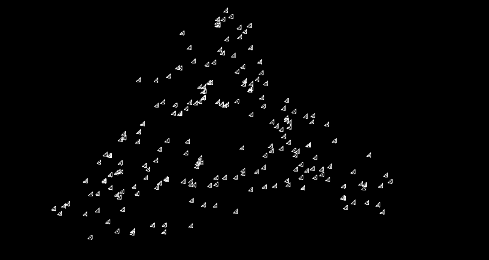 At this point, I wanted to spice it up by
adding trails.
At this point, I wanted to spice it up by
adding trails.
Adding Trails
When creating this project for the first time, the initial solutions
I came up with were underwhelming. One existing solution was to display
the past positions and connect them with straight lines, but that looked
horrible. I searched online on how to create a curve through multiple
points, which is when I stumbled upon the Catmull–Rom
spline, and to my luck, it was already implemented in THREE.js as a
function.
In order to get the trail effect I wanted, I chose to implement
trails as a line. After implementing them, I decided that having a big
circle at the start of each trail looked horrendous, so I removed
them.
Before I could create smooth, curved lines that functioned like a
trail, I first had to track the past positions of all the particles
flying around in our system. Each previous position has to be stored as
a 3D vector to keep track of its x,y,z coordinates. These vectors then
had to be stored in another array so that they could be easily updated
and read while keeping things organized.
To store the previous positions, an array first had to be
initialized. I chose to augment the points array in order to store both
the current and past positions of each line.
Here is our points array right now:
let points = []
for(let i = 0; i < NUM_POINTS; i++){
    let point = new THREE.Mesh(circleGeometry, light_mat)
    point.position.set(Math.random(), Math.random(), Math.random())
    scene.add(point)
    points.push(point)
}
To store the initial and past positions, first the vectors for each
have to be created. Then I would store these values inside another array
before pushing them into the points array:
// inside the for loop:
let past_position = new THREE.Vector3(0,0,0)
let init_position = new THREE.Vector3(Math.random(),Math.random(),Math.random())
let positions = []
positions.push(init_position)
I chose to make the past positions all start at the origin because it
will create an effect where it looks like the simulation all started
from a single point in space. I then made a for loop to put in the 0,0,0
vector into the rest of the array and pushed it into the
points array
// starting at 1 because the 0-index is randomized!
for(let j = 1; j < TRAIL_LENGTH; j++){
    positions.push(past_position)
}

points.push(positions)
Perfect, the points array now stores all the points that my lines
will follow.
To create the lines, I thought I was prematurely optimizing my code
by only creating geometry once (not true, more geometry is created
later) but storing all the line geometry in one array was a great
decision as it allowed me to add each line to the scene exactly once.
Trying to do this in the animate() function would have complicated
things as previous lines in the scene were not automatically deleted. I
started off by creating the geometry and material:
let lines = []
for (let i = 0; i < NUM_POINTS; i++){
    const lineGeometry = new THREE.BufferGeometry()
    const lineMaterial = new THREE.LineBasicMaterial()
    const line = new THREE.Line(lineGeometry, lineMaterial)
    scene.add(line)
    lines.push(line)
}
Now that that’s done, the black screen I got when compiling made
sense as the lines didn’t have their positions updated. To fix this, the
animate function needs to change so that its changing the Vector3
objects inside the points array, which is done like so:
// points[i] --> points[i][0]
for(let i = 0; i < NUM_POINTS; i++){
points[i][0].x += speed * (-alpha * points[i][0].x - 4 * points[i][0].y - 4 * points[i][0].z - (points[i][0].y * points[i][0].y));
points[i][0].y += speed * (-alpha * points[i][0].y - 4 * points[i][0].z - 4 * points[i][0].x - (points[i][0].z * points[i][0].z));
points[i][0].z += speed * (-alpha * points[i][0].z - 4 * points[i][0].x - 4 * points[i][0].y - (points[i][0].x * points[i][0].x));

}
Then I had to update the array so that the current position becomes
the most recent past position. I did this in a for loop that was placed
before modifying the 0-index:
for(let j = TRAIL_LENGTH - 1; j > 0; j--){
    points[i][j] = points[i][j-1].clone()
}
I now have a nested for loop that updates the positions array of each
point. Getting this single of code right took about 20 minutes, between
deciphering what points[i][j].x meant and trying to fix the operation to
properly shift around the Vector3 objects. This was all to fix an error
that caused each vector3 object to have its position changed, but not
being able to access it for whatever reason. After all that, the
positions array now properly updates as time goes on. In order to draw
the lines themselves, I had to feed in each of the arrays that
represents the points of a line into the CatmullRomCurve3 function. the
CatmullRomCurve3 function will create a line that goes through each
point that we feed it, so points had to be used as its
input. I then used the .getPoints method in order to get a list of
points that approximates the shape of the curve:
const spline = new THREE.CatmullRomCurve3(points[i]).getPoints(TRAIL_LENGTH)
The reason I chose to add this complexity in the form of the curve is
because the CatmullRomCurve function gives a nice smooth curve instead
of a very blocky one that would be created by linking the points
together with straight lines. Finally, the position of the line geometry
needs to be updated:
lines[i].geometry.setFromPoints(spline)
The .setFromPoints function creates a buffer geometry that can be
used by the THREE.Line constructor. In this case, I’m using the points
to update the lines position. Before revealing the final product, here
is the entire attractor.js file up to this point. I have added a
“windowResize” function to adjust the height/width of the simulation on
resize.
import * as THREE from 'three'

let scene, camera, renderer;
let NUM_POINTS = 200
let TRAIL_LENGTH = 20

scene = new THREE.Scene();
camera = new THREE.OrthographicCamera(-20, 20, 15, -15, 0, 1000);
renderer = new THREE.WebGLRenderer();
renderer.setSize( window.innerWidth, window.innerHeight);
document.body.appendChild( renderer.domElement );

let points = []
for(let i = 0; i < NUM_POINTS; i++){
    let past_position = new THREE.Vector3(0,0,0)
    let init_position = new THREE.Vector3(Math.random(),Math.random(),Math.random())
    let positions = []
    positions.push(init_position)

    for(let j = 1; j < TRAIL_LENGTH; j++){
        positions.push(past_position)
    }
    points.push(positions)
}

let lines = []
for (let i = 0; i < NUM_POINTS; i++){
    const lineGeometry = new THREE.BufferGeometry()
    const lineMaterial = new THREE.LineBasicMaterial({color:0xff0000})
    const line = new THREE.Line(lineGeometry, lineMaterial)
    scene.add(line)
    lines.push(line)
}

camera.position.set( -23.4, -16.5, -20.7 );
camera.lookAt(scene.position)

window.onresize = function () {
camera.aspect = window.innerWidth / window.innerHeight;
camera.updateProjectionMatrix();
renderer.setSize( window.innerWidth, window.innerHeight );
};

let alpha = 1.4; // don't change; this is part of the math
let speed = 0.01;
function animate() {
    requestAnimationFrame( animate );
    for(let i = 0; i < NUM_POINTS; i++){
        for(let j = TRAIL_LENGTH - 1; j > 0; j--){
            points[i][j] = points[i][j-1].clone()
        }
        points[i][0].x += speed * (-alpha * points[i][0].x - 4 * points[i][0].y - 4 * points[i][0].z - (points[i][0].y * points[i][0].y));
        points[i][0].y += speed * (-alpha * points[i][0].y - 4 * points[i][0].z - 4 * points[i][0].x - (points[i][0].z * points[i][0].z));
        points[i][0].z += speed * (-alpha * points[i][0].z - 4 * points[i][0].x - 4 * points[i][0].y - (points[i][0].x * points[i][0].x));

        const spline = new THREE.CatmullRomCurve3(points[i]).getPoints(TRAIL_LENGTH)
        lines[i].geometry.setFromPoints(spline)
    }
    renderer.render( scene, camera );
}

animate();
This is what I created as the original project.
Click here to see the
final product.
Future of this simulation
This simulation has a few problems. The most important issue: it
doesn’t run well on Firefox. I suspect that there is a memory leak that
eats up enough RAM that it will eventually crash the page but I haven’t
looked into it enough to identify the source of the problem. Second, It
doesn’t work well on Windows 11. I don’t know why; it works fine on
Windows 10. These are problems I’ll eventually fix; For now, I have
other projects I want to work on.
Beyond the problems, there are features I would like to add: -
Allowing the user to play around with the simulation by having input
fields that would allow adjusting the number of lines and adjusting
their length - Adding a dark mode - Coloring the lines, and by
extension, allowing the user to color the lines - Adding in orbit
controls so you could “fly” around the simulation and get different
angles
As initially stated, the point of this blogpost was the describe my
thought process, how I broke down the problem into steps and how I
solved those steps. Writing this post also allowed me to reflect on my
work and refine it significantly. Heres my first iteration of how I
created the curve:
const spline = new THREE.CatmullRomCurve3(curvePoints);
const interpolatedPoints = spline.getPoints(TRAIL_LENGTH);

// Convert the interpolated points to a Float32Array
const verticesArray = new Float32Array(interpolatedPoints.length * 3);
for (let j = 0; j < interpolatedPoints.length; j++) {
verticesArray[j * 3] = interpolatedPoints[j].x;
verticesArray[j * 3 + 1] = interpolatedPoints[j].y;
verticesArray[j * 3 + 2] = interpolatedPoints[j].z;
}

// Update the line geometry with the interpolated points
lines[i].geometry.setAttribute('position', new THREE.BufferAttribute(verticesArray, 3));
lines[i].geometry.setDrawRange(0, interpolatedPoints.length);
Looking back now, it’s not as bad as I thought it was. Instead of
using the .setFromPoints method, I had effectively created the method
manually. I’m not sure what compelled me to change the format of the
vector3’s to float32arrays, but it worked at the time so I went with
it.
For a first time working with 3D graphics, this was a fun adventure.
In the future, I want to make something more interactive.